
Core Working Principle of Dead End Clamps
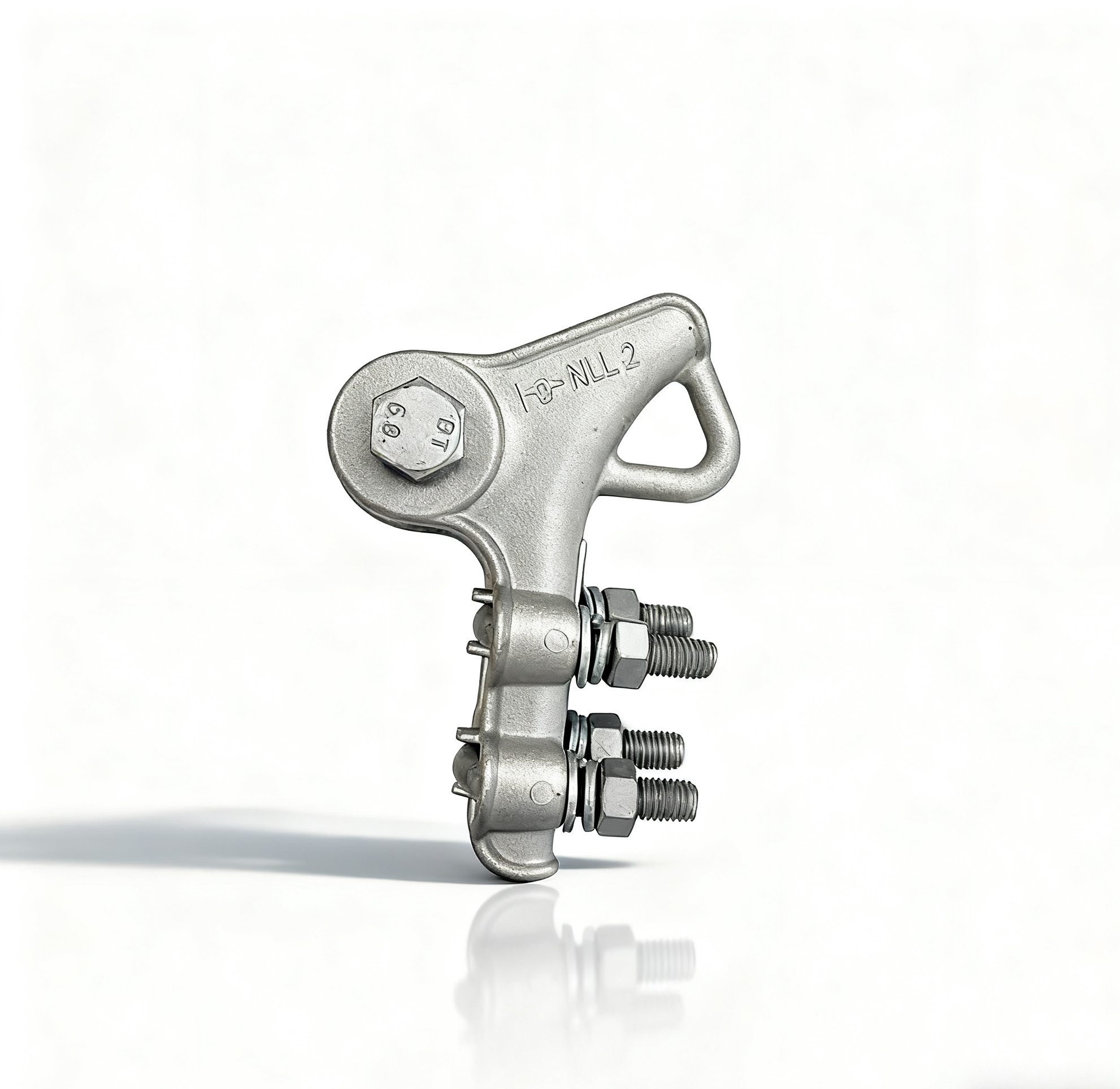
Mechanical Grip Mechanism: Serrated Jaws, Grooves, and Friction-Based Locking
Dead end clamps hold conductors in place by creating friction through their specially designed jaws. These jaws have teeth that actually bite into the wire surface, while grooves help spread out the mechanical stress across the connection point. The way these components work together forms what engineers call a mechanical interlock, which makes sure the tension from the line gets distributed evenly along the conductor. This helps stop wires from slipping when they're under load conditions. Getting the right amount of torque on those bolts matters a lot too. If there's not enough pressure, the clamp won't grip properly. But go too far and softer conductors like AAC or ACSR can get damaged. Field technicians know this well because unlike swage type clamps that need special equipment, bolted versions let workers make adjustments right on site for different wire sizes. This flexibility really comes in handy during both initial installations and routine maintenance checks.
Failure Mode Insight: Conductor Slippage as the Key Indicator of Inadequate Fixation
When conductors start slipping around inside clamps, that's usually a sign something's wrong with the clamp itself. Most of the time this happens because someone installed things incorrectly or used parts that don't fit together properly. If the grooves in the clamp aren't aligned right with how thick the conductor actually is, stress builds up in certain spots which makes the metal wear out faster than normal. We see this problem quite commonly in AAAC systems where there are visible stretch marks forming right next to where the clamp connects. During routine checks, maintenance crews need to watch out for any movement greater than about an eighth of an inch since that means the tension has dropped too low and needs fixing before anything serious happens. Temperature changes definitely make matters worse though. All those expansions and contractions from day to night temperatures slowly work their way through the mechanical connections until eventually everything starts coming loose.
Dead End Clamp Design Types and Their Impact on Fixation Performance
Hydraulic and Swage Clamps vs. Bolted Clamps: Load-Bearing Capacity and Long-Term Reliability
Hydraulic and swage clamps create those permanent compression joints that actually hold about 20 to 30 percent more weight compared to regular bolted versions. That makes these types really good for those high tension power lines where even the slightest slip can cause major problems down the line. On the flip side though, bolted clamps let workers adjust the tension in the field, which comes in handy when dealing with conductors that tend to stretch over time. Studies indicate that if properly tightened according to specs, these bolted connections still maintain around 95% of their original holding power after about a decade facing all sorts of temperature changes. So they strike a nice balance between staying reliable while also being something that maintenance teams can work on without too much hassle.
Material-Specific Selection: Matching Dead End Clamp Type to Conductor (ACSR, AAAC, AAC)
Selecting the right clamp material prevents galvanic corrosion and stress fractures:
- AAC (All Aluminum Conductor): Requires aluminum-bodied compression clamps to avoid electrochemical degradation
- AAAC (All Aluminum Alloy Conductor): Performs best with swage clamps that exploit uniform alloy hardness
- ACSR (Aluminum Conductor Steel Reinforced): Needs dual-material clamps with steel cores aligned to the conductor’s central strand strength
Using zinc-coated clamps on AAC lines increases corrosion rates by 40% due to dissimilar metal contact. Leading utilities now prioritize long-term compatibility over upfront cost, reducing lifecycle maintenance and failure risks.
Tension Management, Stress Distribution, and Safety Implications
Stress Concentration at the Clamp-Wire Interface and Its Role in Fatigue-Induced Failure
When stress builds up at the dead end clamp interface, it tends to create those problem areas we call hotspots, which is where fatigue damage usually starts showing up first. These spots get worse over time when exposed to repeated forces like wind vibrations or changes in temperature, leading to tiny cracks forming in the aluminum strands. Statistics suggest that more than half of all overhead line failures actually come down to this kind of gradual wear and tear happening right at those clamping points. The edges of the clamps themselves become weak spots where these issues kick off. And let's not forget about fretting caused by constant movement either this just keeps eating away at the strands until what was once a safe system becomes increasingly risky across the whole span.
Torque Optimization: Balancing Initial Grip Strength Against Conductor Damage Risk
Getting the right amount of torque on those dead end clamps makes all the difference between protection and damage to the conductor. If there's not enough torque applied, the clamp can slip when loaded, which is a big no-no. On the flip side, cranking it down too tight just crushes the wire strands and creates weak spots where cracks tend to start. Most field workers know they need to stick close to what the manufacturers recommend, usually somewhere around 25 to 40 Newton meters for those aluminum conductor steel reinforced cables. Good practice means grabbing a properly calibrated torque wrench and applying some anti-seize compound first. This helps prevent metal from sticking together during installation and keeps pressure even across the whole contact area. The result? Better grip strength and longer life for the conductor itself.
Standards, Testing, and Real-World Validation of Dead End Clamp Fixation
Testing and setting standards is really important to make sure dead end clamps can handle what they need to for overhead power lines. There are several key standards out there. For example, ASTM B117 looks at how well these components resist salt spray corrosion. Then we have IEC 61284 which checks their ability to withstand UV exposure and general weathering over time. And finally, NF C33-041 focuses on whether they maintain proper torque after going through repeated temperature changes. Utility companies who actually install these things report something pretty impressive too. When everything meets the standards, there's basically no slippage issues. Some systems have been running without any fixation problems for an amazing 30 years even in super harsh coastal areas where salt air eats away at materials. Putting all this together creates a solid reliability standard that helps prevent dangerous situations like conductors falling down or structures collapsing when faced with severe weather conditions.
FAQ
What are dead end clamps used for?
Dead end clamps are used to hold conductors in place within overhead power lines by creating friction through their serrated jaws and grooves.
How do dead end clamps prevent conductor slippage?
Dead end clamps prevent conductor slippage by distributing mechanical tension evenly along the conductor and ensuring proper torque during installation.
What are the differences between bolted and swage clamps?
Swage clamps create permanent compression joints offering higher load-bearing capacities, while bolted clamps allow for field-adjustments and maintain nearly their original holding power over time.
How does conductor type affect clamp selection?
The conductor type affects clamp selection due to material-specific needs such as avoiding galvanic corrosion and ensuring long-term compatibility.
Why is proper torque important in dead end clamps?
Proper torque in dead end clamps is crucial to avoid conductor damage and ensure reliable grip strength.
