
Mechanical Grip Design: How Dead End Clamps Achieve Reliable High-Tension Anchoring
Friction-enhanced locking via serrated jaws and radial grooves
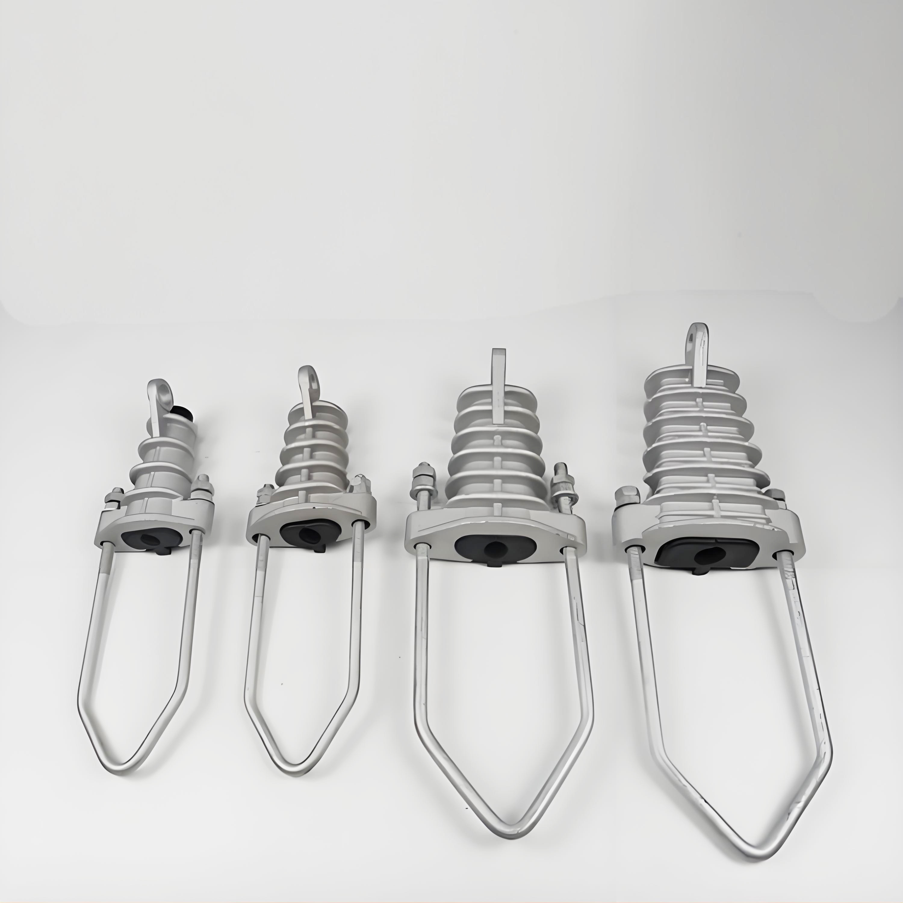
Dead end clamps hold overhead wires in place using pure mechanical grip instead of sticking them down. The clamp has teeth-like serrations that dig into the wire surface, creating way more friction when pulled tight. There are also little grooves running around the sides that spread out the pressure evenly so no one spot gets too stressed. When someone pulls on the wire harder, these design features actually make the grip stronger as the tension increases. Engineers call it a self-locking system because it gets tighter automatically under stress. This kind of setup works great for keeping power lines from slipping loose even during major storms where forces can hit over 50 kilonewtons or after many years of going through hot and cold temperature changes that cause materials to expand and contract repeatedly.
Trade-off analysis: Grip strength vs. conductor surface damage in dead end clamp applications
Getting the right clamping force means finding a sweet spot between strong grip and keeping the conductor intact. When we talk about surface contact, harder materials definitely hold better, but pushing too hard can actually tear up those delicate aluminum strands or mess with the steel core inside. Some research out there indicates that clamps made from aluminum body actually cut down on surface scars by around 37% when compared to those tough steel alternatives. Still, folks need to watch their parameters closely. The grooves shouldn't dig deeper than about 15% of what the conductor measures across, and those little teeth-like features called serrations? They shouldn't angle past 45 degrees either. Industry professionals often turn to solutions like zinc coatings that wear away first or special composite liners designed to soak up tiny abrasions without affecting UTL standards or how well these conductors perform over time.
Load-Bearing Validation: Testing Standards and Real-World Performance of Dead End Clamps
ASTM B117, IEC 61284, and IEEE 1242-2021 test protocols for ultimate tensile load (UTL)
Third party testing is essential for making sure dead end clamps actually reach those important safety marks we all talk about. Take ASTM B117 for example. This standard looks at how well materials resist corrosion by putting them through intense salt spray tests. It's basically fast forwarding time to see what happens after years near the coast or in industrial areas where things get really corrosive. Then there's IEC 61284 which checks if clamps can handle all sorts of mechanical stress over time. Think vibrations from passing trains, temperature changes day to night, and repeated loads similar to what they face on actual power grids every single day. The IEEE 1242-2021 standard goes even further by setting strict rules about ultimate tensile load (UTL) verification. According to this spec, clamps must hold up against forces 20% higher than their rating without bending permanently or slipping loose. All these different standards working together basically prove whether a clamp will stay put when faced with storms, sudden power spikes, or just regular wear and tear over many years. And that means fewer unexpected power failures across the entire electrical network.
Field performance data: UTL exceedance and slippage thresholds for ACSR conductors
Real-world deployments of ACSR conductors validate laboratory findings: compliant dead end clamps consistently exceed minimum UTL requirements by 15–25%, with measured slippage remaining below 0.1 inches under maximum design loads. Long-term monitoring across diverse environments shows:
- Zero catastrophic failures in installations adhering to IEC 61284 torque specifications
- Corrosion-related strength loss under 3% after 10 years in aggressive coastal service
- Slippage maintained within a tight 0.05-inch tolerance despite wind-induced oscillations and ice accumulation
This consistent performance margin ensures reliable conductor alignment, tension control, and structural continuity—even during transient overloads—making standardized validation a non-negotiable criterion for transmission operators.
Stress Redistribution Architecture: Wedge-and-Sleeve Mechanics in Dead End Clamp Systems
Axial-to-radial force conversion through helical compression geometry
What makes the wedge-and-sleeve setup so effective for high tension anchoring? Look no further than those specially machined helical ramps. As the load goes up, these ramps actually turn that dangerous straight line tension into even pressure all around the conductor. We've run simulations and done plenty of real world tests too, showing that this system can spread out forces at a ratio better than 4 to 1. That means much stronger grip while keeping stress distributed evenly across the whole contact area. The friction angles stay right around 7 to 12 degrees, which gives just enough mechanical edge to stop things from slipping without damaging the conductor surface. When someone pulls hard on the cable, instead of creating weak spots, this design turns that straight pull into circular containment. Field engineers love this because it keeps working reliably even when tensions jump past 50 kN, something we see happen regularly in tough installations where standard systems would fail.
Material Durability: Fatigue Resistance and Long-Term Integrity of Dead End Clamp Components
6061-T6 aluminum vs. 316 stainless steel: yield strength, creep behavior, and galvanic compatibility with conductors
Choosing materials affects how long equipment will last for decades to come, and this choice always involves making compromises based on what the specific application needs. Take 316 stainless steel compared to 6061-T6 aluminum. The stainless has better strength numbers around 290 MPa versus aluminum's roughly 241 MPa. It also stands up better to repeated stress, handling millions upon millions of cycles before failing, plus it doesn't stretch out much even when things get hot above 100 degrees Celsius. Aluminum does have benefits though. It weighs less and costs less money, which makes it work well for many lower voltage distribution systems, as long as we watch out for those compatibility issues between metals. When someone tries to attach aluminum clamps directly onto steel reinforced wires like ACSR cables, corrosion problems tend to pop up pretty quickly. That's why most professionals either put isolation sleeves between them, mix in some compatible alloys, or apply special coatings that block electrical reactions. For really important high tension lines where breaking could cause major damage, most engineers still go with 316 stainless steel even though it adds about 65% more weight. They just know from experience that this material maintains its shape and fights off rust much better through all those years in service.
FAQ
What is the primary function of dead end clamps?
Dead end clamps primarily secure overhead wires and prevent them from slipping or loosening by using a mechanical grip system.
How does the wedge-and-sleeve system in dead end clamps work?
This system converts axial tension into radial pressure using helical ramps, ensuring even distribution of stress across the wire for increased grip.
Why are different materials like 6061-T6 aluminum and 316 stainless steel used for dead end clamps?
Different materials are used based on specific needs such as strength, weight, cost, and compatibility with conductors, affecting the longevity and performance of the clamp.
Table of Contents
- Mechanical Grip Design: How Dead End Clamps Achieve Reliable High-Tension Anchoring
- Load-Bearing Validation: Testing Standards and Real-World Performance of Dead End Clamps
- Stress Redistribution Architecture: Wedge-and-Sleeve Mechanics in Dead End Clamp Systems
- Material Durability: Fatigue Resistance and Long-Term Integrity of Dead End Clamp Components
- FAQ
