
The Structural Role of Crossarms in Utility Pole Stability
Understanding how crossarm design influences pole stability
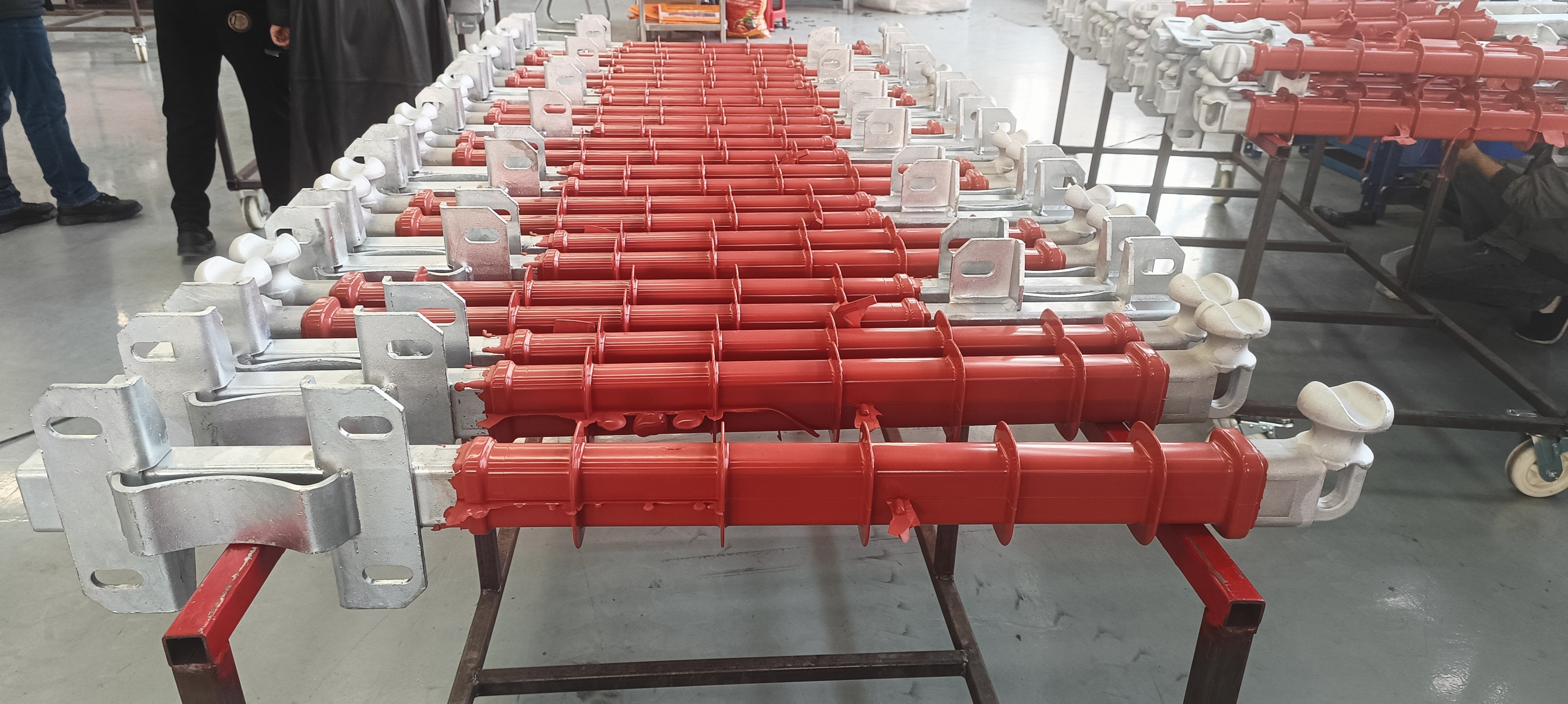
How crossarms are designed plays a big role in keeping utility poles stable while they handle all those electrical lines plus whatever weather throws at them. Wood crossarms just don't hold up as well over time, especially when we're talking about humid areas. A recent study from 2023 on transmission systems showed wood versions start breaking down about 48 percent quicker than these new pultruded glass fiber reinforced polymer ones. Looking further ahead, the 2024 analysis of utility components revealed something pretty telling too. After twenty whole years out there fighting the elements, PGFRP crossarms still have around 92% of their original strength left, whereas regular wood only manages about 62%. That kind of difference makes it clear why choosing the right materials matters so much for infrastructure that needs to last decades without constant replacement.
Key mechanical functions of crossarms in load distribution
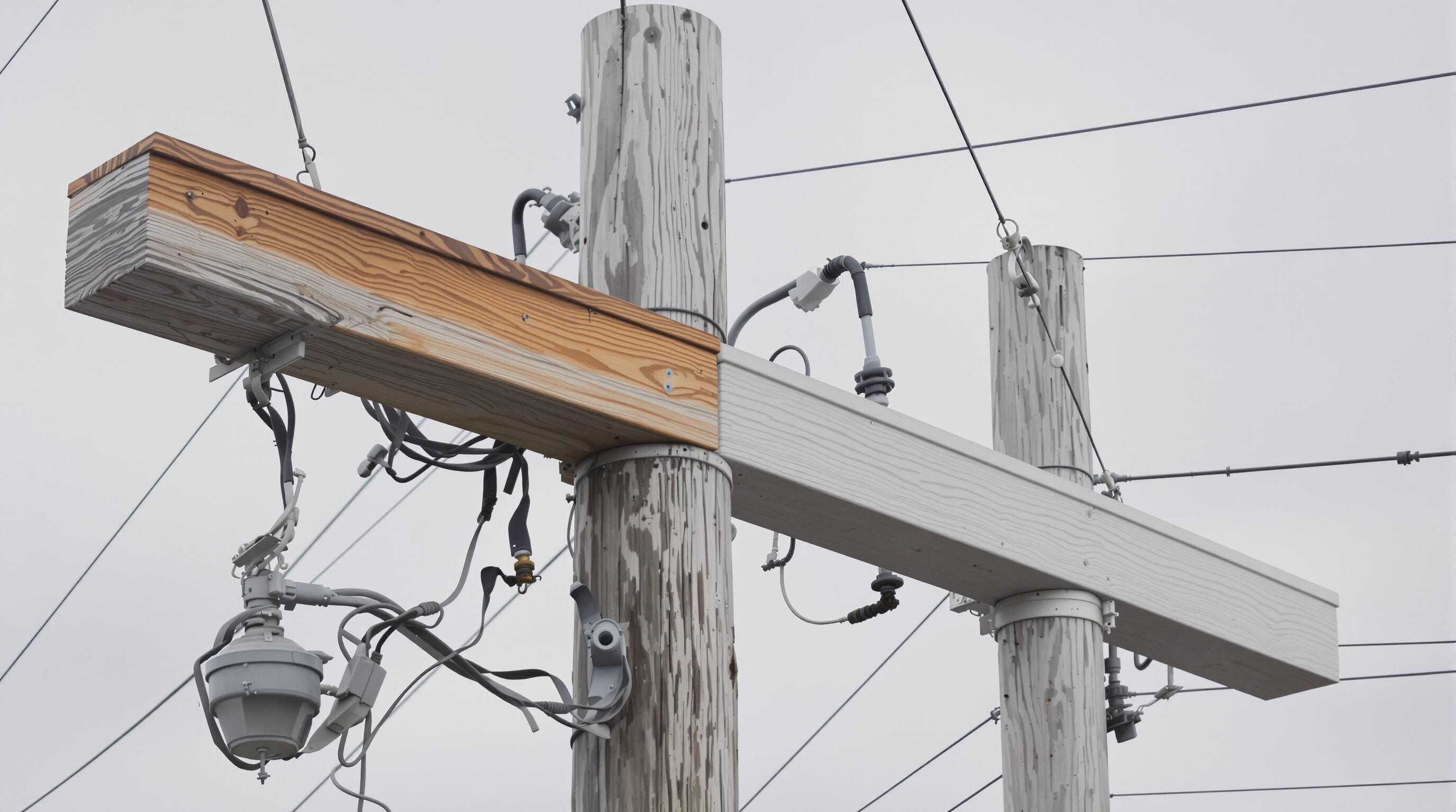
Crossarms do three main things mechanically speaking. They spread out sideways forces on those insulators, hold up against the downward pressure when wires get heavy, and help fight twisting stresses caused by strong winds blowing through the lines. According to some research published last year on grid resilience, better designed crossarms can cut down stress at the bottom of poles by around 34 percent just by sharing the workload more evenly. The newer sleeve reinforced composite versions are really good at resisting shear forces too. These modern ones can take about 31.2 kilonewtons per square meter before they start to bend or deform, which is actually 23 percent stronger than what we see with older models that only handle 25.4 kN/m² before showing signs of wear.
Impact of attachment height and arm length on moment forces
Attachment height and arm length have a nonlinear impact on bending moments, increasing stress on the pole structure.
| Configuration | Arm Length | Height | Moment Force |
|---|---|---|---|
| Standard | 2.4m | 9m | 18.7 kN·m |
| Extended | 3.0m | 9m | 23.1 kN·m (+24%) |
| Elevated | 2.4m | 10.5m | 27.9 kN·m (+49%) |
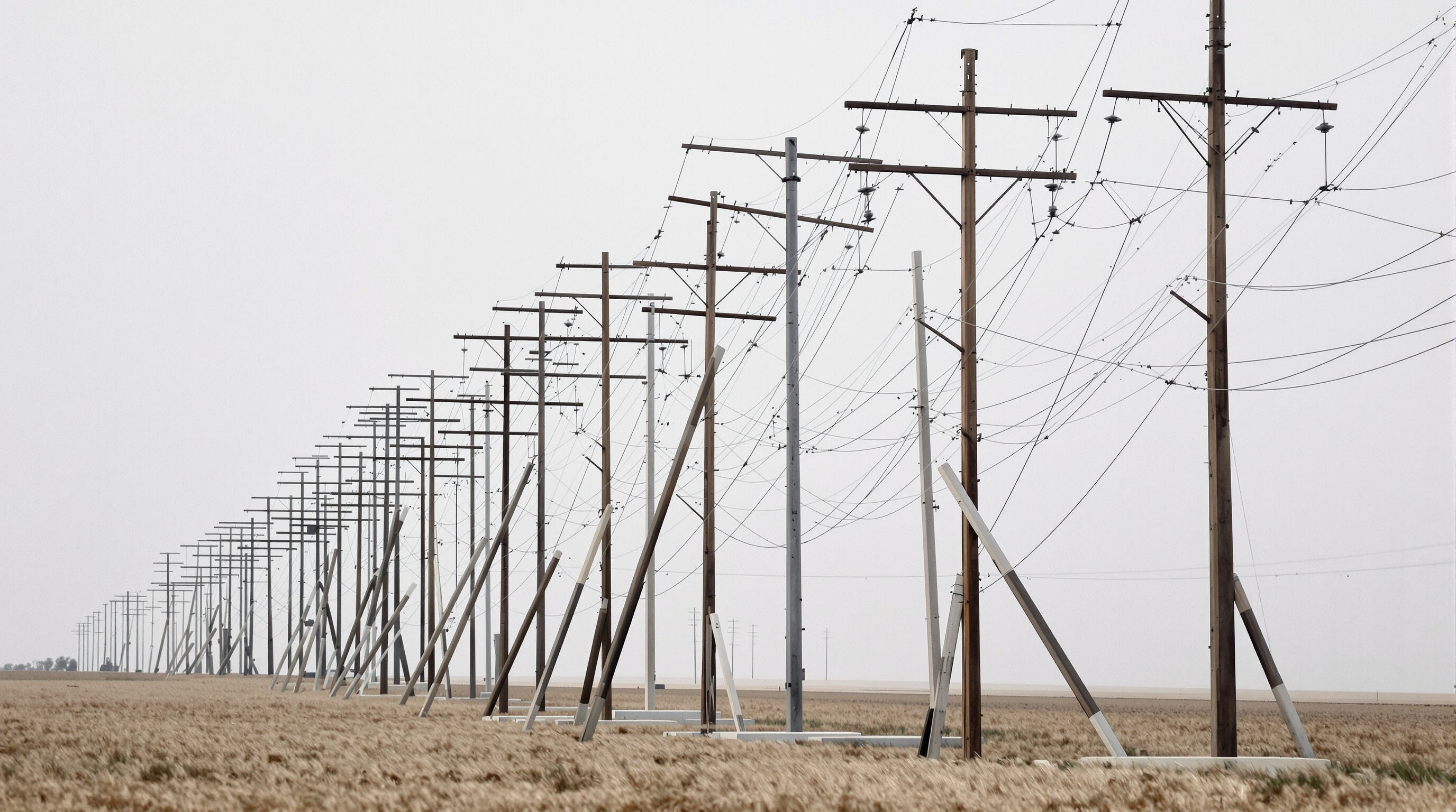
Field analysis of 146 failed poles revealed that 63% of stability issues stemmed from improper arm-length-to-height ratios. Research confirms that keeping crossarms at 30–35% of total pole height optimizes the vertical-to-lateral force balance, reducing the risk of catastrophic failure.
Load Capacity and Material Performance: Wood vs. Composite Crossarms
The structural stability of utility poles hinges on the load-bearing capacity and durability of crossarm materials. Industry testing highlights significant performance gaps between wood and composites under sustained and dynamic loads.
Load capacity of wood and composite crossarms under sustained and peak loads
PGFRP composites exhibit an apparent elastic modulus of 33.50 GPa—nearly double that of wood at 17.95 GPa (Table 4, Load-Deflection Analysis). This enhanced stiffness enables composite crossarms to withstand 2.3Å— higher peak loads in high-tension applications without permanent deformation, making them ideal for demanding configurations.
Failure thresholds in timber vs. fiberglass-reinforced polymer arms
In controlled testing, fiberglass composites demonstrate a 62% higher load threshold before buckling compared to timber. Wood crossarms fail catastrophically under a central point load of 1,727N, whereas PGFRP arms sustain up to 2,709N by efficiently distributing stress across the material matrix.
Long-term degradation effects on load-bearing capability
| Material | Flexural Strength Loss (15 Years) | Critical Failure Mode |
|---|---|---|
| Wood | 40% (humid environments) | Radial cracking from moisture |
| PGFRP Composite | 25% (UV exposure) | Surface delamination |
In salt-air environments, composite crossarms last 270% longer than treated wood. After eight years, PGFRP installations retained over 90% of their initial stiffness, while wooden arms required replacement within three years due to accelerated fungal decay and moisture absorption.
Deflection Behavior and Its Impact on Pole Alignment Under Load
Deflection behavior under load in multi-circuit configurations
The amount of deflection tends to go way up as we add more circuits to support. Testing on controlled beams reveals something pretty striking actually - when multiple circuits are involved, the deflection at point of failure jumps around 97% compared to what happens with just one circuit setup. When conductors aren't arranged symmetrically, they create these twisting forces that mess with how stress gets distributed across the structure. Looking at simulation data, engineers have noticed that crossarm systems supporting five circuits bend about 35% more in the middle section than those handling only three circuits, even when facing exactly the same wind conditions. This kind of difference matters a lot in practical applications where structural integrity is critical.
Measuring sag-induced misalignment in high-tension spans
Engineers use LiDAR mapping to detect deflection-induced pole tilt, with field data showing 12–18 mm of horizontal misalignment per 100 meters in 230kV corridors. When angular displacement exceeds 2°, a condition found in 17% of inspected spans, structural integrity becomes compromised. Real-time monitoring systems now track deflection in relation to:
- Conductor tension fluctuations (±15% from nominal)
- Temperature-induced sag (3–5 cm per 10°C change)
- Ice accretion (up to 25 mm radial buildup)
Trend: Increasing use of pre-cambered crossarms to offset deflection
Utilities are increasingly adopting pre-cambered crossarms with a 15–20 mm upward arch to counteract expected deflection. This design reduces corrective maintenance by 42% in coastal regions, based on a 12-month deflection mitigation trial. Manufacturers achieve this through:
- Material optimization: Fiberglass composites with a 34 GPa flexural modulus
- Load testing: Validation at 150% of rated capacity over 72 hours
- Topography-based calibration: Custom camber profiles tailored to regional wind and ice conditions
Field results from long-term deployments show pre-cambered units exhibit 35% less mid-span deflection after five years compared to flat crossarms.
Environmental and Operational Challenges to Crossarm Stability
Effect of moisture, UV exposure, and temperature swings on crossarm integrity
The environment really takes its toll on crossarms over time. Wood is particularly vulnerable since it can soak up around a quarter of its own weight in water, which cuts down on structural integrity somewhere between 12% and 18%, according to research from Ponemon back in 2023. Fiberglass reinforced plastic (FRP) does better against moisture but has problems with UV damage. After being exposed to sunlight for years, these materials start showing wear on the surface and lose about 40% of their shear strength after ten years. The daily temperature changes we see across most regions—from freezing cold at night to scorching heat during the day—cause all sorts of expansion and contraction cycles. This constant movement creates tiny cracks in both wooden and FRP crossarms. Recent studies looking at material breakdown in 2024 showed that places with extreme temperature fluctuations actually cut the life expectancy of FRP crossarms by roughly 30% when compared to areas where temperatures stay relatively constant.
Ice loading and wind shear as amplifiers of crossarm-induced instability
The build-up of ice really ramps up the mechanical load on infrastructure. Just think about it - a simple 2 inch thick layer all around a crossarm actually weighs in at roughly 1,800 pounds extra. And when those icy conditions meet wind speeds over 55 miles per hour, things get serious fast. The sideways force hits about 1,200 pounds per foot, which is way too much for most pole structures to handle. We saw this firsthand during last winter's brutal ice storms across North America. Out of all the failed crossarms, nearly 8 out of 10 were victims of wind shear effects. Most didn't break because the materials gave way, but rather because the metal fasteners simply wore out over time. What makes matters worse is how these combined stresses change the natural vibration pattern of poles themselves. For lattice towers specifically, this creates resonance issues that are actually four times more likely than normal.
Innovations in Crossarm Design for Improved Long-Term Stability
Utility providers are adopting three key innovations to combat degradation and enhance structural reliability:
Smart Crossarms with Embedded Strain Sensors for Real-Time Monitoring
Composite crossarms now integrate fiber-optic sensors that detect micro-strain variations with ±0.5% accuracy. These systems enable continuous structural health monitoring, identifying internal cracks in wood crossarms up to 72 hours before visible signs appear, allowing for timely intervention.
Strategy: Transitioning from Reactive to Predictive Maintenance Using Deflection Data
Machine learning models analyze historical deflection patterns to predict crossarm lifespan and fatigue progression. Utilities leveraging predictive analytics report 40% fewer unplanned outages by replacing components at 80% of their theoretical fatigue limit, avoiding failure-based maintenance.
Emerging Materials: Hybrid Composites and Nano-Treated Timber
Recent tests show sleeve-reinforced composite crossarms maintain 66% of their original stiffness after 20 years of simulated service—more than double the 25% retention in untreated wood. This hybrid design reduces vertical deflection by 45.3% under ice loading compared to conventional materials, marking a significant advancement in long-term stability.
FAQ
What materials are commonly used for crossarms on utility poles?
The most common materials used for crossarms are wood and glass fiber reinforced polymers (PGFRP). PGFRP is increasingly preferred due to its higher durability and strength over time.
How does the design of crossarms impact the stability of utility poles?
Crossarm design influences the distribution of mechanical forces on utility poles, including lateral, downward, and twisting stresses. Properly designed crossarms can reduce stress at the base of poles and improve the distribution of loads.
Why is it important to consider the arm-length-to-height ratio in utility poles?
An appropriate arm-length-to-height ratio helps optimize the vertical-to-lateral force balance, reducing the risk of structural failure and enhancing overall utility pole stability.
How do environmental factors impact the integrity of crossarms?
Environmental factors such as moisture, UV exposure, and temperature swings can significantly degrade crossarm materials. Wood absorbs moisture, leading to structural weakening, while UV exposure affects fiberglass crossarm surfaces.
What innovations are being employed to enhance crossarm stability?
Innovations include the integration of fiber-optic sensors for real-time monitoring, using predictive maintenance strategies, and the development of hybrid composites and nano-treated timber for long-term stability.
Table of Contents
- The Structural Role of Crossarms in Utility Pole Stability
- Load Capacity and Material Performance: Wood vs. Composite Crossarms
- Deflection Behavior and Its Impact on Pole Alignment Under Load
- Environmental and Operational Challenges to Crossarm Stability
- Innovations in Crossarm Design for Improved Long-Term Stability
-
FAQ
- What materials are commonly used for crossarms on utility poles?
- How does the design of crossarms impact the stability of utility poles?
- Why is it important to consider the arm-length-to-height ratio in utility poles?
- How do environmental factors impact the integrity of crossarms?
- What innovations are being employed to enhance crossarm stability?
